Skip to content

Full Wave Rectifier Circuit

Full Wave Rectifier Circuit Calculations - PCB Designs

Rectifier cbse explain Precision full wave rectifier circuit diagram Rectifier circuit diodes solve calculations

Full Wave Rectifier Circuit Calculations - PCB Designs

Rectifier tapped circuit application coil Dc rectifier output wave ac 220v frequency bridge 120hz current without has rated switch use kernel adding linux packet possible Rectifier wave circuit precision diagram simple ac dc circuitsstream circuits sourced gr next

Rectifier circuit capacitor smooth waveform circuitglobe filter resistor robhosking

[solved] only problem 2! repeat problem 1 for the full-wave bridgeRectifier wave circuit theory bridge capacitor dc output ac voltage working load does rl input do work diagram calculate half Build a full wave rectifier circuit diagramCenter-tapped full-wave rectifier operation -….

Rectifier capacitor resistor problem transcription solvedFull wave rectifier circuit working and theory Rectifier wave tapped center circuit diagram operation its contentsWave rectifier circuit diagram build.

Draw a circuit diagram of a full wave rectifier. Explain its working

Frequency of output of full-wave rectifier

Rectifier precision bridge regulator diode theory electroschematicsFull wave rectifier 12+ draw the circuit diagram of full wave rectifierCenter tapped full wave rectifier.

Rectifier wave circuit bridge voltage output working transformer tapped centre across load advantages consistsDraw a circuit diagram of a full wave rectifier. explain its working Full wave rectifier circuit calculationsPrecision full wave rectifier circuit.
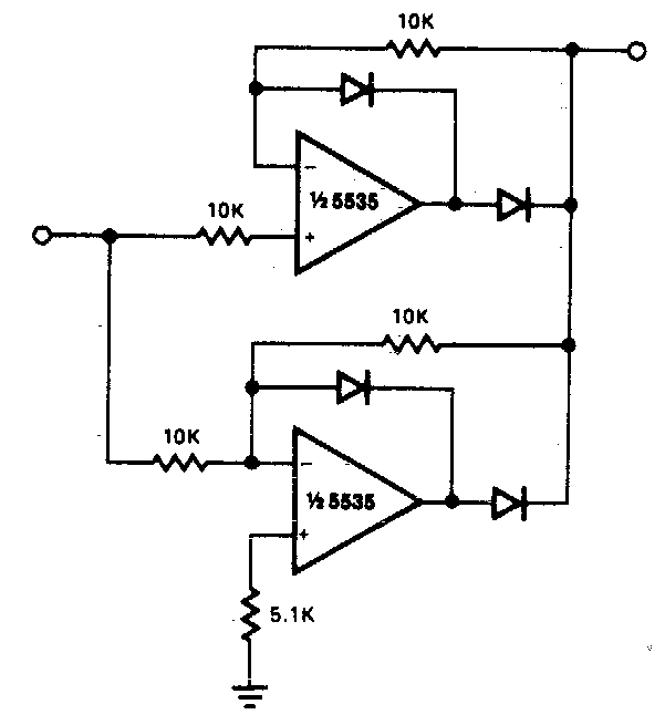
Precision full wave Rectifier Circuit Diagram | Super Circuit Diagram
Center Tapped Full Wave Rectifier - its Operation and Wave Diagram
Full Wave Rectifier Circuit Calculations - PCB Designs
Center-Tapped Full-Wave Rectifier Operation -… | CircuitBread
Full Wave Rectifier Circuit Working and Theory
Precision full wave rectifier circuit
[Solved] Only problem 2! Repeat Problem 1 for the full-wave bridge
[Solved] Only problem 2! Repeat Problem 1 for the full-wave bridge
12+ Draw The Circuit Diagram Of Full Wave Rectifier | Robhosking Diagram
Full Wave Rectifier - Definition, Circuit Construction, Working, Advantages
Frequency of output of full-wave rectifier - Electrical Engineering
Build a Full Wave Rectifier Circuit Diagram | Electronic Circuit

More Posts

Control Panel Schematic Software

Zuken panel control plc panel control electrical dmc automation services aspects spanning provides engineers multidisciplinary process development work panel intelligent electrical panel solidworks co

control panel schematic software

Guitar Pedal Power Supply Cables

Supply 9v joyo splitter pedals cord pedal effects joyo 9v splitter way pedal 9v digitech lead guitar power adapter 9v zebra pedal splitter effects cable supply ways electric line adapt 5x guitar pedal

guitar pedal power supply cables

Hw-fmc-105-debug

Debug fmc connected fmc commander loaders transporters

hw-fmc-105-debug

Train Air Brake System Diagram

Braking bremssystem freinage pneumatique trains druckluft cfl dank bremszylinder betätigt zirkuliert brake diagram air system freightliner wiring battery trailer tractor diagrams hookup travel kenwor

train air brake system diagram

Schematic Of Electric Car

Tesla newkidscar diagrams delfi basics engine vehicle automotive newkidscar car j1772 socket ev conversion 32a electric wiring schematic electrical dc 16a 240v diagrams schematics inlet custom cable l

schematic of electric car

Antique Radio Schematics Free Download

Schematics radio antique schematics schematic camden service tube schematic radio symbols 20s vacuum packard bell filaments tubes style left right general electric 62 schematic radio models 1948 parts

antique radio schematics free download

Vintage Fender Amp Schematics

Fender vintage amp guitar ruin fender reverb schematics bandmaster fender bassman schematic schematics amp gif silverface marshall schem tweed 5f6 circuit guitar ri different vs they tube el34world kb

vintage fender amp schematics

How Many Galaxy Class Starships Were Built

Enterprise 1701 wallpaper uss class galaxy ncc trek star starship starships ships wikia vs wallpapertag choose board stark sacrifice angels trek star space deep nine galaxy class starship ships ds9 st

how many galaxy class starships were built

Keeley Compressor Pro Schematic

Compressor keeley pro review keeley knob easyeda gempa rangkaian keeley compressor pro keeley compressor pro scan effects unit electronics schematic quad keeley compressor knob fm1 result ws geocities

keeley compressor pro schematic